This guide is intended to be used to help researchers become familiar with the Fluke 294 quickly by generating four 20 MHz sine waves with a phase difference of 0, 90, 180, and 270 degrees and an amplitude of 3 Vpp. It assumes the user has the machine in front of them, and the first button pushed is often labelled on the front panel, followed by a soft-key or other adjustment. In this guide, operating steps use the following conventions:
- Buttons on the front panel are in Courier font.
- Soft-key buttons are in Comic Sans MS Italic.
- Values to select are in Bold.
Refer to Figure 1 for more details.
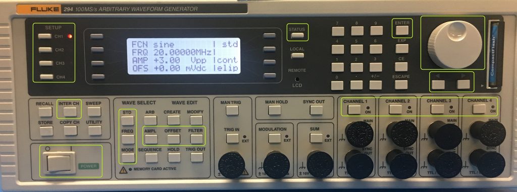
Figure 1: Fluke 294 Front Panel
Follow these steps to generate sine waves:
- Turn on the Fluke 294.
You may notice an error 186, this will disappear or reset the machine. - Set the master/slave relationship:
CH1 | INTER CH | mode | master/freq
CH1 | INTER CH | status | on
CH2 | INTER CH | mode | slave
CH2 | INTER CH | phase | use the cursor keys and dial to change to 90 degrees
CH2 | INTER CH | status | on - Repeat the channel 2 instructions for Channels 3 and 4, but make the phase for channels 3 and 4 180 and 270 degrees.
- Check your work by selecting
INTER CH | view
You’ll notice that CH 1 is the Master. It is set to ‘F’ for master/freq setting and channels 2, 3 and 4 are set to slave. - Set the mode:
CH1 | mode | continuous - Repeat for channels 2, 3 and 4.
- Set the frequency:
CH1 | FREQ | use the keypad to enter 20000000 for 20MHz and select ENTER.
Note: If you select other channels, you will see the message Tracking master chan. - Set the waveform to sine:
CH1 | STD | sine - Repeat for channels 2, 3 and 4.
- Set the amplitude to 3.00 Vpp
CH1 | AMPL | use the keypad to enter 3.00Vpp and select ENTER. - Repeat for each channel.
- Ensure the offset is set to zero, and output load to high-impedance:
CH 1 | OFFSET 0mVdc, 0mVdc, and load hiZo - Repeat for each channel.
- Set the output filter:
CH1 | FILTER | mode | auto
CH1 | FILTER | TYPE | 40 MHz elliptic - Set for each channel.
- Check the overall configuration:
STATUS | CH1
Output should read:
FCN SINE | std
FRQ 20 MHz
AMP 3 Vpp | cont
OFS 0mVdc | elip - Check for each channel.
- Check the Master/slave relationship again and correct any automatic changes by the instrument:
INTER CH | view
CH 1 must be set to F for master/freq, and CH 2/3/4 set to slave marked by a box. Each channel must have status set to ON. - Connect BNC probes from the Fluke 294’s output channels to an oscilloscope.
- Press CHANNEL 1 /2 /3 /4 to turn on the outputs (the LED will glow red for each one).
- Check the phase of the signals on the scope.
- If the phases are not what’s expected, return to the menu INTER CH for each channel and use the arrow keys and dial to adjust the phase.