This guide was first published in 1999, as a reference for students designing integrated circuits (IC’s) who then were expected to test performance of their devices as bare die or in packages, as proof of both fabrication and design execution.
Since that time, enhanced frequency range, stringent power demands and the variety of applications have pushed developers to exceed the limitations imposed by older fab equipment, a more rudimentary understanding of semiconductor physics, and integration possibilities. The original chapters in this guide have not lost their usefulness, though. Rather, this guide has increased in value as engineers and scientists have toiled to produce machines that build upon each discovery, involving sensors, analog and digital circuits, optics, microfluid channels and clever packaging, and place them within reach and the imagination of those who embrace progress for the betterment of society.
We thank those who have contributed in years past to this guide, and ask subscribers to continue their work by offering opinions and ideas to us that will keep these pages as valuable as the day they were published.
1.1 Purpose of This Guide
Why test?
The importance of proper test measurements cannot be overemphasized. A design is not trustworthy until it is proven to work. Accurate testing involves not only assembling and connecting the proper equipment, but planning which measurements will be performed, and in what order; knowing how to conduct the proposed tests and how to interpret their results; and, of key importance, designing a chip for testability. Establishing a comprehensive test plan early in the design phase is a key to successful testing, and getting precise measurement results requires a proper understanding of measurement system components and their interaction.
What does this guide cover?
This High-Speed Circuit Test Guide introduces basic RF/microwave measurements and provides study references for RF/microwave designers who wish to test their circuits or make their circuits readily testable. Specific configurations for the characterization of RF/microwave amplifier linear and nonlinear behavior are described for several measurements of interest, including:
- Basic S-parameter measurements;
- Swept amplifier compression third-order intercept (TOI);
- Noise figure.
A Smith Chart , Used for S-parameter Graphing
These descriptions will cover the test equipment and components involved, the rationale for choosing particular components, and common sources of error. It is recommended that the reader learn why each component is used in a test bed, and then design a setup or adapt the representative setups we show to suit specific applications and desired accuracy. We include a section providing references on performing mixer characterization, and another section that gives some basic procedures on voltage-controlled oscillator (VCO) characterization.
To help the reader avoid problems, this guide includes recommendations pertaining to RF and microwave testing, such as:
- Tips for handling and probing loose dice;
- Tips on equipment handling and care;
- Tips for improving measurement accuracy;
- Interpretation of results;
- On-wafer measurement techniques.
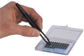
Using static-safe tweezers to pick up die
A glossary has been compiled and included, though we presume that the reader is already aware of many terms used throughout the guide. We have added sectional references that are designed to supplement the guide text. There are many good application notes available from some manufacturers’ web sites. The reader is encouraged to obtain these references when further clarification is needed. Chapter 6 lists some starter links for searches.
Who needs this guide?
The guide was written for IC designers, interested in developing or building upon their expertise at circuit speeds in excess of 5 GHz; who need to test such circuits; who need to plan for test in the early design stage; and/or who want a refresher in the basics of high-speed analog circuit test. Anyone with a general interest in this subject will benefit from the introductory section in Chapter 2, Preparing to Test.
United States Spectrum Allocation Chart (*.pdf)
Showing the position of microwave raditaion on the frequency spectrum.
By no means should one expect to become an expert by reading only this guide. While the reader will gain insight through study, practical experience may only be gained by resolving testing issues as they arise in a lab.
1.2 Overview of Measurement Considerations
Types of Devices
Devices can be classified as linear or non-linear:
- When stimulated by a sinewave, a linear device will produce an output wave that has changed only in magnitude and phase, and no new signals are added. This is still a form of distortion, since the criteria for a distortionless linear device is that the amplitude (magnitude) response must be flat, and the phase response must be linear, over the bandwidth of interest. Examples of these devices are filters, cables, inductors, capacitors or resistors.
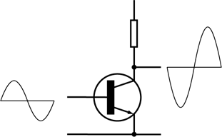
- A non-linear device produces output signals that include new frequency components not present at its input. Many components behave linearly under small-signal conditions but exhibit nonlinear behavior if driven by a large enough input signal. This is also true for some passive devices, such as filters, which often contain magnetic material that displays hysteresis effects. Active devices such as amplifiers and mixers are included in this category.
The RF test sections of this guide focus on amplifiers exhibiting both behaviours. The complete characterisation is achieved with stimulus-response measurements, mostly using a single continuous wave signal as a stimulus, swept over frequency or power.
Linear measurements also apply to nonlinear devices that are biased to operate in their linear region. Linear device measurements involve making a variety of magnitude and phase measurements that compare the device’s output signal to the incident signal provided by an RF source, to quantify such things as:
- gain/loss;
- gain flatness;
- group delay;
- isolation (reverse transmission);
- output power;
… and the comparison of reflected signal to the incident signal to determine such parameters as impedance, VSWR, and return loss at all ports of the DUT.
Return loss is associated with reflected measurements, and insertion loss is associated with transmission measurements. The majority of the transmission/reflection measurements are made using a network analyzer performing, as the name implies, high-frequency network analysis.
Note that all RF and microwave amplifiers exhibit some nonlinear behaviour under certain conditions. Some nonlinear measurements require more complex stimuli, such as broadband sources for noise measurements, or multiple signal inputs to measuring intermodulation distortion. These measurements often involve spectrum analyzers, or noise figure meters, and often employ swept power inputs. Other common nonlinear measurements include gain compression and harmonic distortion.
Pulsed RF and pulsed-bias conditions may be used to test devices that lack the required heatsinking to permit continuous operation. They are also used when small-signal measurements do not accurately predict large-signal operation.
Pulsed testing is common for the wafer-level measurements of high-power devices but this type of test is not discussed in this guide.